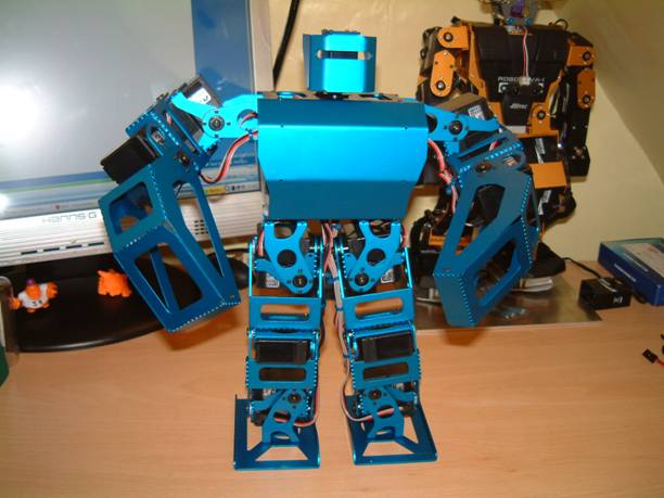
Building the Graupner RB1000 By Jason Huntley (Rep001)
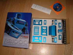
On opening the box it was very clear that the layout, and the building sequence had been thought about and upon reading the manual, in CD format this proved to be the case.
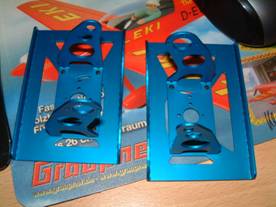
So first parts to be made up where the feet. Simply a foot plate and an ankle bracket attached thus.
The Head is then screwed to its bracket and then screwed to the top plate of the torso which you will see later.
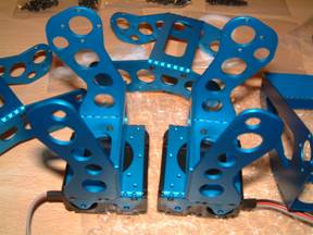
Then on to the 6 x 2 DOF units. One each
for the foot/ankle, hip/leg and the shoulder/arms. Pay careful attention here
as I made the mistake of making them all the same. They are in fact handed (3
of each) and that took a while to sort.
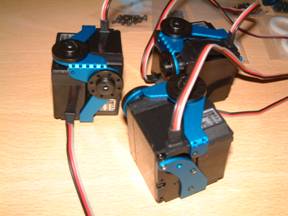
I liked the way the brackets wrap around the servos and everything is a perfect fit and lines up as you would expect. This was the first stage that used lots of screws and I am unsure why they choose Philip style heads instead of a nice Hex drive but choose the correct screwdriver and all is well
Next we are on the main torso/chassis of the RB. This will house the control board and battery.
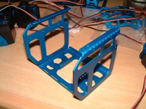
From here in things start to take shape. Onto the Torso you add the shoulder stubs and the hip servos. The control board mounts to a chassis plate in the Torso so this is also added now along with first stages of the legs, the hip brackets.
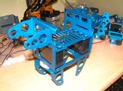
Note: Nylon rub spacer on the hips
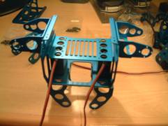
Next is to centre all the servos before the horns are attached. Everyone will have a slightly different method for this but I stacked the servos as they would be on the RB and went through them all that way. The servos are banked in 7’s on the board with the red toggle switch bank at the bottom ( 1 starts top right,15 starts top left )
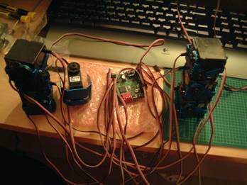
Here is a picture of all brackets assembled and ready for the final stage.
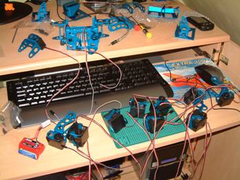
So lets get him together. Adding the arms and legs is next after joining the feet to the lower leg bracket and finally the hip joint. Once all that is complete he should like like this.
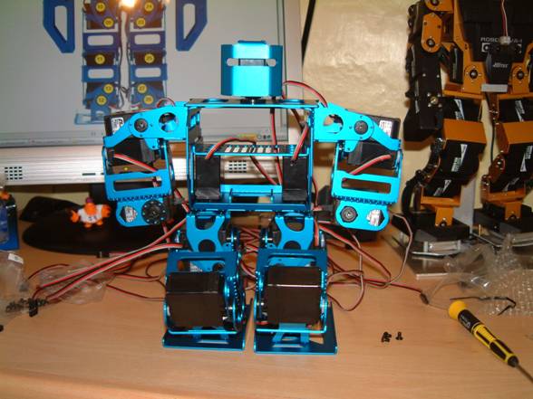
Holding up gives a clearer picture of everything so far.
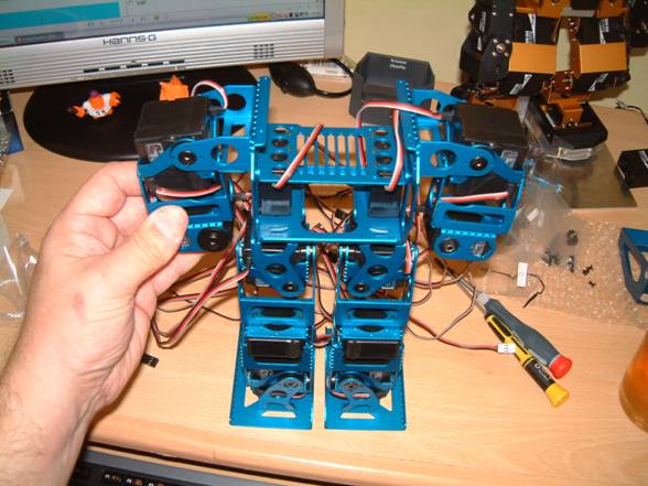
Next step is to route the wiring as best you see fit. The Manual is very unclear on this with only a couple of pictures but it all becomes clear as you start threading them through. I ended up with 4 clusters tied together to give me easy recognition of where they came from. So 2 for arms R/L and 2 for the legs R/L.
Screw his hands on when you are sure that the servos are all centred correctly as they can rub on his thighs (scratching)
And that’s about all. The back plate needs the rubber stops sticking on and the front chest plate screwed into place.All that is left is to see the little chap moving which I will cover next……….