Currency
|

Mobile Robots require continuous DC power supply to ensure the computers and motors continue to work when swapping batteries or when switching from DC to battery operation or when using an unreliable DC power supply backed up by battery. RoboSavvy HotSwap Power Board (PowerBoard 1.0) is designed to provide up to 25A of continuous power, allowing safe hot-swapping between two interchangeable power sources.
| 2 Input power sources (mains DC power or battery) | The board can accept any combination of two power sources. They can be of different voltage within the 2.9V-18V range. |
| 2.9V to 18V Operating Range | Good for up to 4 cell LiPo |
| Emergency power cutoff when power source reaches low battery voltage | Protect you LiPo battery from critical low voltage |
| Voltage spike protection | The Board turns off when reaching voltage above 18V |
| Input Voltage Inversion protection | Protects the board and system from accidental reversed polarity input voltage |
| Protection from from applying erronous external voltage on output rail | Protects the board from application of high voltage or reverse polarity voltage on the Output rail |
| Current spike cuttoff | The board will shut off the output voltage when sensing a current spike. Limits Peak Fault Current in ≤1μs |
| Inrush current control | Protects against initial current spike surge |
| Protects Output Voltage from Input Brownouts and oscilations | Ensures limited voltage drop when switching input voltage source |
| Status LEDs and monitoring pins | LEDS indicated current input channel source and fault. This status is available as pins to external CPU for monitoring. |
| Pins allow enable/disable of each input source | User/CPU can select which input voltage is available |
The board comes in three possible configurations:


| Number of input power sources | 2 |
| Input Voltage range (V) | 2.9V-18V |
| Number of output power rails | 1 |
| Rail maximum continuous current | 25A |
| Rail maximum spike (peak) current | 50A for 0.12ms |
| Indicator LEDs | 4 |
| Enable/disable power sources | One for each input |
| Quick response on hotswap | 15ms |
| Inrush current limit | prevent sparks |
| Overcurrent protection | Allow 25A-50A for 120μs |
| Overvoltage protection | 20V |
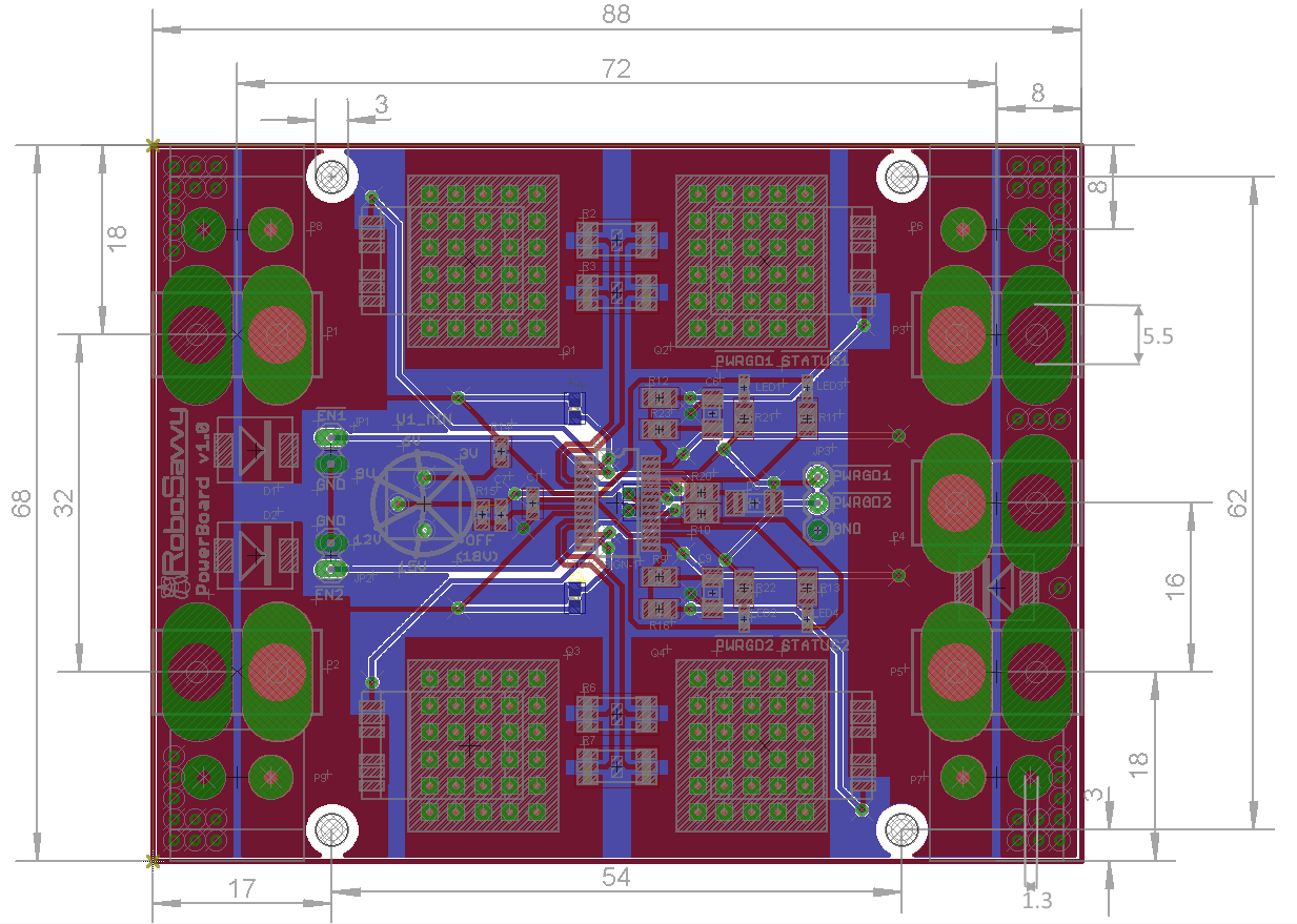
| Measurements | 88mm x 68mm |
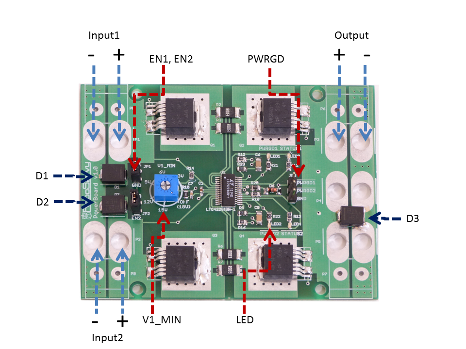
| Input1, Input2 | Input voltage Channlel 1,2 (2.9V-18V) | 2.9V-18V |
| Output | Output rail will route any or none of the Input voltages. There are several types of connectors and locations that the user can choose to solder the output | 2.9V-18V |
| EN1, EN2 | Enable Input1, Input2 by grounding JP1,2. The JP1,2 pins produce 1.235V and will source 10μA. Any voltage above 1.235V applied to JP1,2 will disable the Input. Any voltage 1.235V or lower will enable the Input. | 10μA |
| PWRGD1,2 | "Power Good" indicates which of Input1 and Input2 is currently sourced | 5V=on, 0V=off |
| LED1,2 | Which Input is currently sourced (PWRGD status). LED1=Input1, LED2=Input2 | Green |
| LED 3,4 | Fault Indicators - neither Input1 nor Input2 are routed to the Output until the board is reset. LED3=Fault caused by Input1, LED4=Fault caused by Input2. Types of fault: (a) short-circuit in the output (b) current limit reached (c) low voltage threshold reached on both Input1, 2 | Red |
| D1, D2 | TVS Diode protects against Input overvoltage and voltage inversion (Reverse Polarity) on Input1 and Input2. User replaceable. | SMLJ17A |
| D3 | Same as D1,D2 but protecting the board and target system from overvoltage and reverse polarity on the Output rail. Also protects from electrostatic discharge (EDS) | SMLJ17A |
| Hotswap IC | The main chip in charge of the hotswap logic | LTC4228-1 |
| MOSFETs | Rated for 20V, 100A | AUIRFS8409-7P |
The board has two current limiting features. When the board is initially powered, the Inrush Control feature kicks in and prevents from current spikes and sparks from occuring. When the board is working continously, the current is limited to 25A. The Output will be cut off if the current spikes between over 25A and 50A for a period exceeding 120μs. Once the Output is switched off, the board goes into Fault mode (indicated by LED3,4) and needs to be reset. If the current spikes to more than 50A during the 120μs period, it may overheat and damage the MOSFETs.
| Feature | Description |
|---|---|
| Inrush current control | Limits maximum current output linearly when board is initially powered. The timing depends on input Voltage at 0.2V per millisecond. For example, 10V Input will limit current uptake during 50ms. 20V Input will limit the current uptake during 100ms. |
| I > 25A, t=0 | If current exceeds 25A, the clock starts ticking.. |
| 50A > I > 25A, t < 120μs | The current is allowed to continue its surge between 25A and 50A for up to 120μs |
| I > 50A, t < 120μs | Fault Condition is triggered if the current goes beyond 50A |
| 50A > I > 25A, t > 120μs | Fault Condition is triggered if the current stays above 25A for more than 120μs |
Both Input rails and the Output rail have a Transient-Voltage-Suppression (TVS) Zener diode soldered between the + and - rails (D1,D2,D3). The diode will assume all the flowing current should the voltage exceed the rated 18V-24V or should an inverted voltage be applied. Should these fault conditions happen, the board and system will be saved but the diode may be damaged as heat accumulates through prolonged exposure to the current.
Rotate the potentiometer V1_MIN to the minimum voltage value of Input1 (the priority channel). If the input voltage on Input1 is above the set value, then the Output will be taken from Input1. If the voltage on Input1 goes below the set value, the Output will be connected to INPUT2. When the Input1 voltage is then again higher then V1_MIN, the voltage source will swap again. When the board has hot-swapped to Input2, no checks are done on Input2 voltage level. If Input2 is a LiPo battery, please use a "LiPo saver"/"battery monitor" to prevent it from reaching critical low voltage
| Input | Output |
|---|---|
| Input1 > V1_MIN | Input1 |
| Input1 < V1_MIN | Input2 |
| Input1 < V1_MIN, Input2 < V1_MIN | Does not create a fault condition |
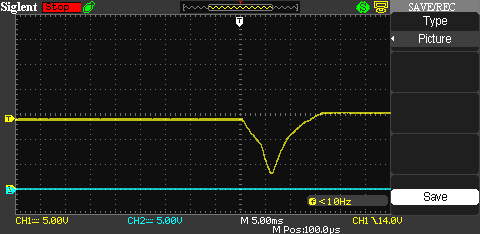
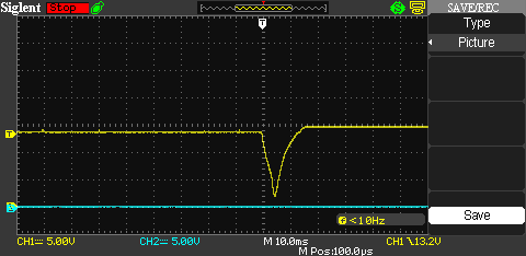
In the following two diagrams we tested the board with incandescent light bulbs, a 4-cell LiPo battery and DC power. The DC power was in Input1 and when it disconnected, the voltage resumed taking the LiPo in Input2 as source. When the light bulbs consumed 10A, the transition took 15ms and the lowest voltage resitered was 3V. When the light bulbs consumed 20A, the transition took 7ms and the lowest voltage resitered was 1.8V. Our test represents the "worst case" scenario since incandescent light-bulbs have negligeable inductance. When the target circuit has capacitance, the transition voltage drop is hardly noticeable.