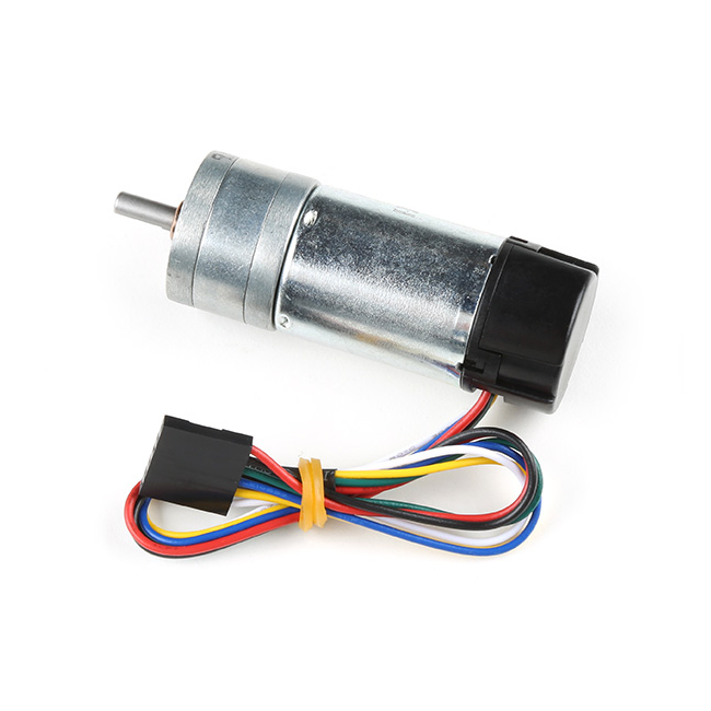
Metal Gearmotor with Encoder - 12V (9.7:1)
This gearmotor consists of a low-power, 12 V brushed DC motor combined with a 9.68:1 metal spur gearbox, and it has an integrated 48 CPR quadrature encoder on the motor shaft, which provides 464.64 counts per revolution of the gearbox’s output shaft. The gearmotor is cylindrical, with a diameter just under 25 mm, and the D-shaped output shaft is 4 mm in diameter and extends 12.5 mm from the face plate of the gearbox.
A two-channel Hall effect encoder is used to sense the rotation of a magnetic disk on a rear protrusion of the motor shaft. The quadrature encoder provides a resolution of 48 counts per revolution of the motor shaft when counting both edges of both channels. To compute the counts per revolution of the gearbox output, multiply the gear ratio by 48. The motor/encoder has six color-coded, 8″ (20 cm) leads terminated by a 1×6 female header with a 0.1″ pitch.
The Hall sensor requires an input voltage, Vcc, between 3.5 and 20 V and draws a maximum of 10 mA. The A and B outputs are square waves from 0 V to Vcc approximately 90° out of phase. The frequency of the transitions tells you the speed of the motor, and the order of the transitions tells you the direction.
Note: The listed stall torques and currents are theoretical extrapolations; units will typically stall well before these points as the motors heat up. Stalling or overloading gearmotors can greatly decrease their lifetimes and even result in immediate damage. The recommended upper limit for continuously applied loads is 4 kg⋅cm (55 oz⋅in), and the recommended upper limit for intermittently permissible torque is 8 kg⋅cm (110 oz⋅in). Stalls can also result in rapid (potentially on the order of seconds) thermal damage to the motor windings and brushes; a general recommendation for brushed DC motor operation is 25% or less of the stall current.
Features:
- Voltage: 12V
- Stall Current: 0.9A
- No-Load Current: 60mA
- Gear Ratio: 9.7:1
- No-Load Speed (RPM): 580
- Stall Extrapolation: 1.3 kg⋅cm (18 oz⋅in), 0.9 A
- Max Power (W): 1.8
| Manufacturer | SparkFun |
|---|


